Ammeters are connected in series with whatever device’s current is to be measured. A series connection is used because objects in series have the same current passing through them. (See Figure 21.28, where the ammeter is represented by the symbol A.) Figure 21.27 (a) To measure potential differences in this series circuit, the voltmeter (V
I need help identifying these components. 1) what are the displays on the watch. 2) where can I find a dial like this? : r/AskElectronics
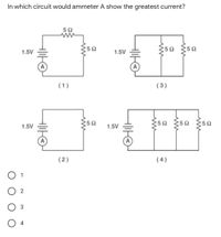
Question Transcribed Image Text: In which circuit would ammeter A show the greatest current? 5Ω {50 §50 1.5V 1.5V (1) (3) ;5Ω 5Ω 5Ω 1.5V 1.5V (2) ( 4 ) O 1 3 O 4 Expert Solution Trending now This is a popular solution! Step by step Solved in 2 steps with 4 images SEE SOLUTION Check out a sample Q&A here Knowledge Booster Learn more about

Source Image: issuu.com
Download Image
Ammeters Measure Electrical Current. A meter designed to measure electrical current is popularly called an “ammeter” because the unit of measurement is “amps.”. In ammeter designs, external resistors added to extend the usable range of the movement are connected in parallel with the movement rather than in series as is the case for voltmeters. This is because we want to divide the

Source Image: shutterstock.com
Download Image
Investigating Electrical Circuits Kit – Arbor Scientific | Series and parallel circuits, Basic concepts, Digital ammeter Due to the ammeter’s very low resistance, it will “draw” a lot of current from the voltage source. In effect, the ammeter will form a short circuit with the voltage source, potentially damaging the meter and/or the source. In applications where the voltage source possesses very little internal resistance of its own, the current surge resulting from such a short-circuit may be huge.
Source Image: bartleby.com
Download Image
In Which Circuit Would Ammeter A Show The Greatest Current
Due to the ammeter’s very low resistance, it will “draw” a lot of current from the voltage source. In effect, the ammeter will form a short circuit with the voltage source, potentially damaging the meter and/or the source. In applications where the voltage source possesses very little internal resistance of its own, the current surge resulting from such a short-circuit may be huge. Using voltmeters and ammeters to measure potential difference and current. Google Classroom. A student wants to measure the current through the resistor R 2 for the circuit below. Where should the student hook up an ammeter to measure the current through resistor R 2 ?
Answered: In which circuit would ammeter A show… | bartleby
Project Overview In this project, you will learn how to use an ammeter to measure electrical current (the flow of electricity). Typically, the ammeter is one of the functions of a multimeter, which is an electrical instrument capable of measuring voltage, current, and resistance (Figure 1). Figure 1. A Voltmeter, Ammeter & Cell are Connected in Series. Ammeter shows No Deflection. Why?

Source Image: electricaltechnology.org
Download Image
For the circuit shown in the figure, what current does the ideal ammeter read? | Homework.Study.com Project Overview In this project, you will learn how to use an ammeter to measure electrical current (the flow of electricity). Typically, the ammeter is one of the functions of a multimeter, which is an electrical instrument capable of measuring voltage, current, and resistance (Figure 1). Figure 1.

Source Image: homework.study.com
Download Image
I need help identifying these components. 1) what are the displays on the watch. 2) where can I find a dial like this? : r/AskElectronics Ammeters are connected in series with whatever device’s current is to be measured. A series connection is used because objects in series have the same current passing through them. (See Figure 21.28, where the ammeter is represented by the symbol A.) Figure 21.27 (a) To measure potential differences in this series circuit, the voltmeter (V

Source Image: reddit.com
Download Image
Investigating Electrical Circuits Kit – Arbor Scientific | Series and parallel circuits, Basic concepts, Digital ammeter Ammeters Measure Electrical Current. A meter designed to measure electrical current is popularly called an “ammeter” because the unit of measurement is “amps.”. In ammeter designs, external resistors added to extend the usable range of the movement are connected in parallel with the movement rather than in series as is the case for voltmeters. This is because we want to divide the

Source Image: pinterest.com
Download Image
What Is the Pinch-Off Voltage for a JFET? – ElectronicsHacks DC Circuits Fundamentals of Electricity ByEditorial Updated On August 1, 2018 Current is the measure of the rate of flow of electric charges across the conductor. It is measured in the unit of Ampere. This current measurement in a circuit is mostly done by Ammeter. Ammeter Ammeter measures the electric current in the circuit.

Source Image: electronicshacks.com
Download Image
DC Series circuits explained- Resistance, Voltage, and Power consumption Due to the ammeter’s very low resistance, it will “draw” a lot of current from the voltage source. In effect, the ammeter will form a short circuit with the voltage source, potentially damaging the meter and/or the source. In applications where the voltage source possesses very little internal resistance of its own, the current surge resulting from such a short-circuit may be huge.
Source Image: electroniclinic.com
Download Image
In the above circuit, if the current reading in the ammeter A is 2A, what would be the value of R1? – YouTube Using voltmeters and ammeters to measure potential difference and current. Google Classroom. A student wants to measure the current through the resistor R 2 for the circuit below. Where should the student hook up an ammeter to measure the current through resistor R 2 ?

Source Image: m.youtube.com
Download Image
For the circuit shown in the figure, what current does the ideal ammeter read? | Homework.Study.com
In the above circuit, if the current reading in the ammeter A is 2A, what would be the value of R1? – YouTube Question Transcribed Image Text: In which circuit would ammeter A show the greatest current? 5Ω {50 §50 1.5V 1.5V (1) (3) ;5Ω 5Ω 5Ω 1.5V 1.5V (2) ( 4 ) O 1 3 O 4 Expert Solution Trending now This is a popular solution! Step by step Solved in 2 steps with 4 images SEE SOLUTION Check out a sample Q&A here Knowledge Booster Learn more about
Investigating Electrical Circuits Kit – Arbor Scientific | Series and parallel circuits, Basic concepts, Digital ammeter DC Series circuits explained- Resistance, Voltage, and Power consumption DC Circuits Fundamentals of Electricity ByEditorial Updated On August 1, 2018 Current is the measure of the rate of flow of electric charges across the conductor. It is measured in the unit of Ampere. This current measurement in a circuit is mostly done by Ammeter. Ammeter Ammeter measures the electric current in the circuit.
